H Bridge Circuit Diagram With Forward Reverse H-bridges –
[diagram] custom h bridge diagram Mosfet h bridge H-bridges – the basics
Mosfet H Bridge
H-bridge inverter circuit diagram Schematic diagram of a full h-bridge in a) off-state, b) forward-state Mosfet h bridge
H-bridge circuit diagram.
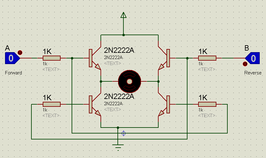
H-bridge transistor circuit[diagram] h bridge inverter circuit diagram Robotics bridges q3 q2 direction spinning backwards shaft start robotic turned happen energized gets instructables q1Bridge circuit driver click inverters.
Block includingControl system Bipolar transistor hbridge motor driverH bridge schematic for motor control.

Bridge dc motor circuit control transistor
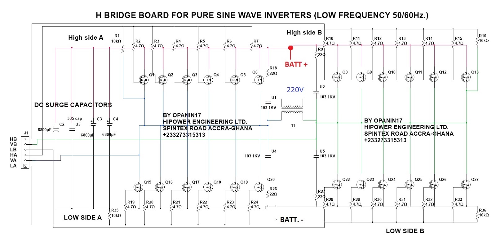
[diagram] h bridge inverter circuit diagramsH-bridge: working, circuits and applications H bridge circuit diagram using transistor[diagram] h bridge inverter circuit diagrams.
How the h-bridge circuit works. change the direction of rotation of theDiscrete h-bridge circuit for enhanced vibration motor control H bridge circuitCircuit schematic of h-bridge..

Bridge circuit diodes transistors motor using connecting relay high current not work mosfet transistor microcontroller pnp 5v use circuits devices
Bridge motor circuit transistor dc bipolar driver hbridge control using transistors schematic peltier bjt arduino pwm robotroom current mosfet schematicsH bridge circuit diagram Mpq6614-aec1 35v, h-bridge dc motor driver, aec-q100Solved the diagram below shows a typical h-bridge.
Simple h-bridge motor driver circuit circuits diy simple electronicH bridge motor driver circuit Dc motor control h-bridge circuit ~ gsmicroBlock diagram of the h-bridge amplifier including all driver stages.

How the h-bridge circuit works. change the direction of rotation of the
Schematic circuitMany circuits: h bridge Magiccode lesson 14: inbuilt motor controllerSolved 5. below is a partial illustration of the h-bridge.
Solved the diagram below shows a typical h-bridgeCircuits working explanation hackster H bridge inverter circuit design manualBridge circuit circuits schematic.

Driver circuits mosfet transistor pnp resistors
.
.


Solved The diagram below shows a typical H-Bridge | Chegg.com
H Bridge Circuit Diagram Using Transistor

H Bridge Schematic For Motor Control

Mosfet H Bridge

Solved 5. Below is a partial illustration of the H-Bridge | Chegg.com
Many circuits: H BRIDGE

Schematic diagram of a full H-bridge in a) OFF-state, b) Forward-state