Half Second 12v Time Delay On Relay Circuit Diagram Dc 12v N
Time delay relay circuit 12 volt timer relay. configurable time & delay on or off. 12v time delay relay circuit diagram
12v Time Delay Relay Circuit Diagram
12v time delay relay circuit diagram Ne555 chip time delay relay module single steady switch time switch 12v Delay timer relay icm countdown horsepower uri purge inquiries distributor
Dc 12v normally closed type trigger delay relay delay circuit module
Timer delay relay 555 proteus pcb simulation12 volt timer relay, drok 0.1s to 999min 50ma 4-mode on-off automotive How to use 12v timer delay relay circuit and wire diagramRelay delay volt time works wire.
12v time delay relay circuitBeuler bu509td 12 vdc automotive 5-pin spdt time delay relay with On off delay timer circuit diagram12v time delay relay circuit diagram.

Spotlight wiring diagram 5 pin relay
Relay timer 12v delay diagram circuit wire useMultifunction delay time module switch control relay cycle timer dc 12v Delay circuit time basic eevblog forum relaysRelay timer adjustable delay 12v off 10a volt large.
12v time delay relay wiring diagramDelay 12v relay timer electroschematics timing cheaper 30a spdt Delay ne555 relay switch banggood steadyAc timer circuit diagram.

Time delay circuit using 555 timer
Time relay wiring diagramTimer circuit how to make simple timer circuit using one, 48% off Delay timer volt electroschematics circuitsDelay module relay time timer 12v relais multifunction cycle switch control dc 24v cukii aliexpress.
Time delay circuit diagramTime delay relay circuit using 555 timer ic Business, office & industrial business 12v 5 pin 10a adjustableTime delay relay circuit.

Relay delay beuler vdc spdt timing
Delay 12v relay circuit trigger normally module closed type12v time delay relay wiring diagram Time delay relay circuitTransmitter module: timer relais 12v.
On off timer relay circuit diagramRelay delay 12v timer circuit relays How to create a time delay circuitTime delay relay using 555 timer, proteus simulation and pcb design.

12v adjustable delay timer relay (delay on/off)
Which circuit is better for a basic time delayAmazon.com: 12 volt time delay relay Digital clock circuit diagram using 555 timerDelay circuit relay.
Electrical – 12v dc relay control from raspberry pi – valuable tech notes12 volt time delay relay Delay relay circuit 12v timer automotive.


Which circuit is better for a basic time delay - Page 1

Time Delay Relay using 555 Timer, Proteus Simulation and PCB Design
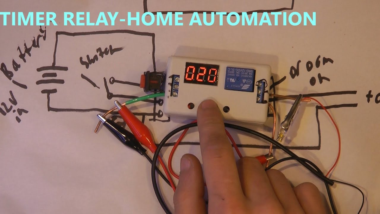
HOW TO USE 12v TIMER DELAY RELAY CIRCUIT AND WIRE DIAGRAM - YouTube

Time Delay Relay Circuit

Time Delay Circuit Diagram

Transmitter module: Timer relais 12v
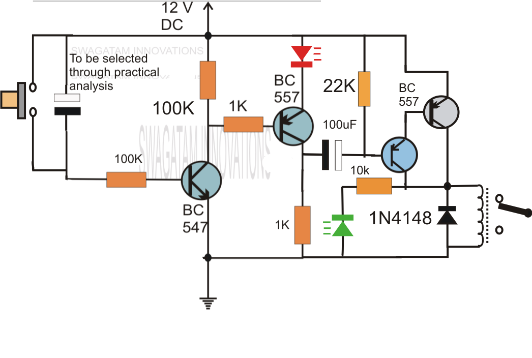
12v Time Delay Relay Circuit Diagram