Hall Sensor Wiring My Hall Sensors Has 6 Wires Instead Of 5.
Linear hall-effect sensor – working and application circuit – homemade Hall effect current measure solar sensor arduino transducer sensors pv ac clamp connect honeywell energy dc battery power Hall effect abs sensor measurement
[DIAGRAM] Hall Effect Sensor Wiring Diagram - MYDIAGRAM.ONLINE
Hall effect flow sensor circuit – help with pulse/counter input circuit Chapter 9. sensors Hügel ich habe durst kommandant brushless motor hall sensor wiring
Hall effect sensor wiring
Sensor hall wiring wire hallsensor work proximity learning magnetic does magnet ledSensor diagram wiring hall vems primary trigger rpm sensors figure 10pcs cs3020 hall sensor effect hall switch circuit hall effect sensorsHall effect sensors.
Magnetic hall effect sensor allegro a1302 : leo bodnar electronicsMultipurpose hall effect sensor circuit Sensor arduino hall effect pro maker uno using code rpm simple connections interfacing diagram use connect read tutorial easy digitalHall sensor control v.s. no-hall – how to tell the difference..
![[DIAGRAM] Hall Effect Sensor Wiring Diagram - MYDIAGRAM.ONLINE](https://i2.wp.com/i.stack.imgur.com/2diRi.png)
Brushless motor hall sensor wiring
Emerging technologies: hall effect sensor a3144Using ratiometric hall effect sensors Nos urb-eHall effect sensors sensor switch switches circuits tutorial using ratiometric.
Hall effect sensors sensor diagram wiringHall sensor wiring Hall sensor ebike difference controller tell control sensors identify betweenMy hall sensors has 6 wires instead of 5... how do i connect them? what.

Sensor wiring k100 chyme
Sensor hall effect switch wiring diagram[diagram] hall effect sensor wiring diagram [diagram] hall effect sensor wiring diagramA3144 sensor hall effect diagram connection arduino wiring digital sensors 24v.
Sensor a3144 datasheet pinout encoder components circuits monofindia using components101 elektronik disimpanHall sensor wiring Using a hall effect sensor with arduinoA3144 hall effect sensor, pinout diagram, description & datasheet.

Hallsensor \ learning \ wiring
Hall sensor connectionsCircuit diagram Hall effects sensor with dc motorWires sensors hbs configuration.
Hall effect sensor switch wiring diagramArduino sensor lab magnetic schematics ky az Hall effect sensor circuit linear using diagram circuits wiring sensors amp op switch amplifier magnetic homemade opamp application workingHelp! rfi is triggering my interrupts!.

My hall sensors has 6 wires instead of 5... how do i connect them? what
Abs draads sensors meten overzicht schematisch aansluiten tiepieHall effect or reluctor? Linear hall-effect sensor – working and application circuit – homemadeHow to connect hall effect sensors and picto measure the solar pv energy??.
Hall effect circuit linear sensor application diagram magnetic working circuits homemade sensors proximity field into simpleHall sensor wiring phase urb .


Hall Effect Flow Sensor Circuit – Help with Pulse/Counter Input Circuit

Brushless Motor Hall Sensor Wiring

Using a Hall Effect Sensor with Arduino - Electronics-Lab
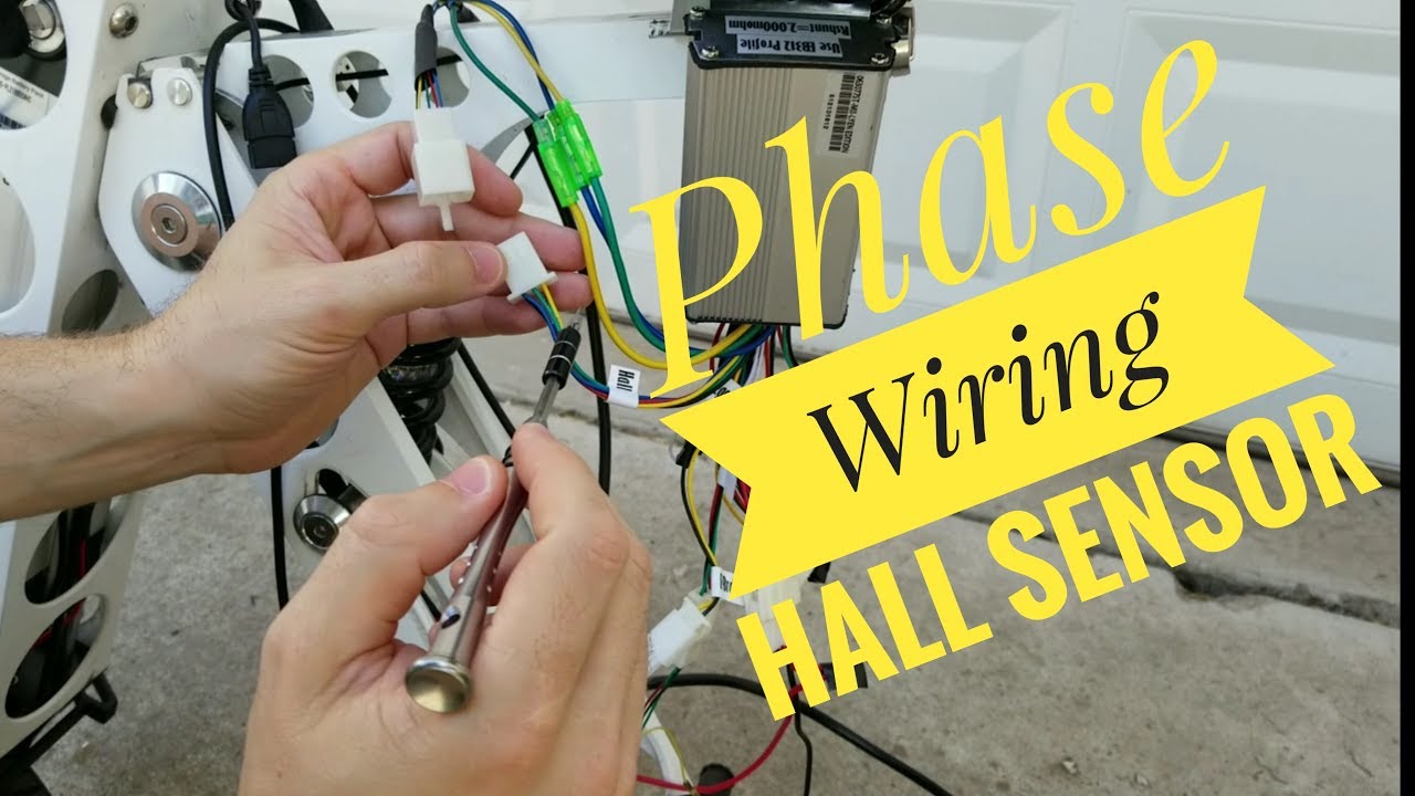
NoS URB-E - MODS: Phase & Hall Sensor Wiring - YouTube

How to connect hall effect sensors and PICto measure the solar PV energy??

Chapter 9. Sensors
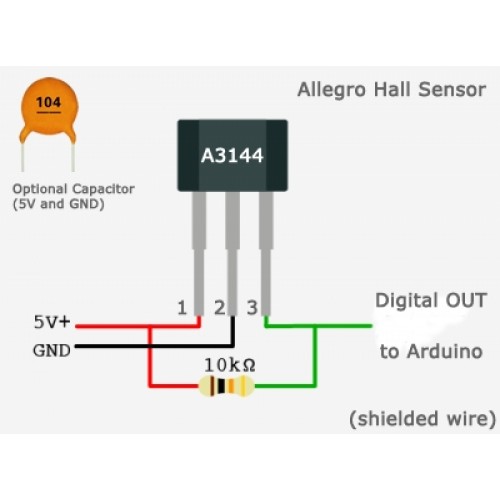
EMERGING TECHNOLOGIES: Hall Effect Sensor A3144